As electronic devices continue to increase in power and
decrease in size, the problem of heat management has become more
complex. When designing electronic enclosures for harsh
environments every aspect of cooling must be optimized. The
advanced Product Development Group at Miltope Corporation has
turned to Computational Fluid Dynamics (CFD) to help achieve
proper cooling requirements in new product designs.
Coolit is a Windows 95/NT based program that models
fluid flow and heat transfer of electronic systems using CFD
methods. Unlike many analysis programs, Coolit is
specifically designed to model electronics and electronic
enclosures. This allows the user to easily create system level
models using various standard electronic components such as
cabinets, printed circuit cards, fans, and heat sinks.
Coolit is based on a graphical user interface (GUI)
which allows the user to create models by first beginning with
the enclosure, creating components and complex components, and
then positioning the components within the enclosure.
Characteristics, such as size, position, and properties, of the
enclosure and components can be easily changed with the use of
pull-down menus or by pop-up menus through the GUI. Once the
model is complete, Coolit will automatically generate a
grid. This grid can then be modified if required. Finally the
model is solved and the computed results are graphically
displayed. Graphical results include temperature, velocity
vectors and total velocity, heat flux vectors and total heat
flux, pressure, and turbulence intensity.

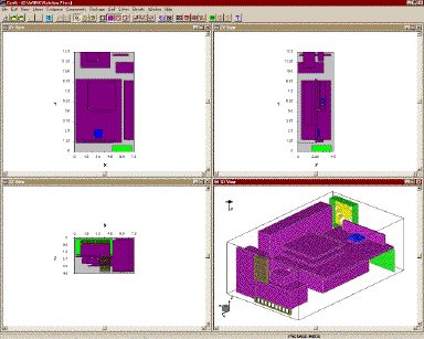
The GUI provides three orthogonal projections and one
isometric view of the model in either wire frame or solid
perspective. All views can be zoomed in or out and the isometric
view can be rotated to allow easy access to all components. The
intuitive menu makes it easy to step through the creation of a
model from the enclosure, to adding components, solving the
problem, and displaying the results.
Coolit was used to model the electronic enclosure shown
below in figure 1. This was a relatively complex model, which
included an enclosure with 1 fan, 2 vents, and 15 various
components. Also include were 2 volume resistance models used to
simulate heat sinks. The grid was generated and modified to
produce approximately 115,000 nodes. This model was solved with
an algebraic turbulence model for convection and conduction
through the solid components. The solution was obtained in 261
iterations and about 5 hours on a 233 MHz Pentium PC with 96 Meg
of memory.
The model was first created with the size and placement of the
cooling vents based on intuitive thinking, which was to use vents
as large as possible. It was determined by the CFD model and
later verified with lab testing that intuitive thinking can be
very distant from the optimal design. By using the graphical
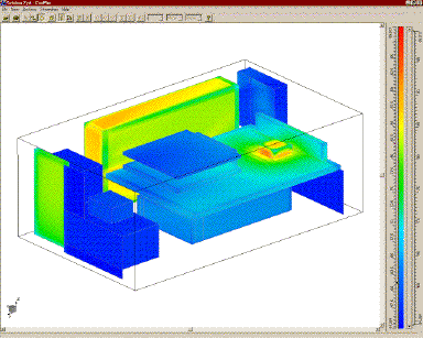
display to view plots similar to that shown in figure 2, the
initial results showed that one particular integrated circuit
chip was reaching very high temperatures and would require a heat
sink for normal operation. This was easily added to the model by
first creating a volume resistance and then placing it on top of
the integrated circuit.

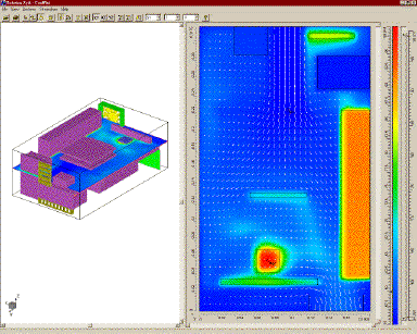
More importantly, Coolit provided a graphical display
of the flow field within the enclosure, showing the high velocity
areas versus the stagnate areas. Velocity vectors and total
velocity can be displayed on either of the XY, XZ, and YZ planes
as shown in Figure 3. It was found that by reducing the size of
the vents and placing them in the correct positions, the majority
of airflow could be concentrated over the hot components. By
using the pop-up menus, both the size and positions of the vents
were varied until the optimal layout was determined. The final
configuration was found more quickly and at a minimum cost when
compared to iterative testing on physical models.

Coolit has other features that make it simple and easy
to use. Changes to the model, which do not effect the grid
generation, can be made and the solution found based on the
previous results. This can drastically reduce computation times
when testing several configurations. The software is also capable
of handling any combination of predefined units or custom units
when creating models. For example, length can be in inches,
temperature in Kelvin, and power in watts. The results can also
be displayed and re-displayed using different units or custom
units. In addition, the program can solve problems while using
your PC to do other work. Although computation times will
increase by multitasking, Coolit will not completely
tie-up your PC.
Coolit comes with a user manual. It is fairly easy to
read and includes tutorials to help you learn to create and solve
models very quickly. An on-line help menu compliments the user
manual. I was able to use the software to create models like the
one shown above in about a week. Although I have gained some
experience with CFD while in college, I did not attend a Coolit
training course prior to using the software.
Mike Staiano is a Mechanical Engineer with Miltope
Corporation. Miltope specializes in the ruggedization of computer
equipment and peripherals for commercial, industrial, and
military use. Coolit software allows Miltope to optimize the
thermal design aspects of electronic enclosures without the extra
time and cost of physical testing.