CFD (computational fluid dynamics) is helping Raytheon E-Systems Div.
shorten its design cycle time and eliminate costly and time-consuming
redesign steps. Using an easy-to-learn, desktop version of CFD thermal
modeling software, the military electronics leader is detecting potential
thermal problems early in the development cycle when engineers have maximum
flexibility in packaging design and component placement. Early detection
eliminates costly redesign, which according to RaytheonĚs Dan Jones, senior
principal engineer, "often accounts for most of the cost".
Raytheon E-Systems develops a variety of ruggedized, military electronics
systems. The equipment includes an assortment of communications boxes,
plus phased-array antenna systems, specialized computer systems and other
associated equipment. Increasingly this equipment combines custom designs
with commercial off-the shelf boards as part of the military's thrust
to reduce program costs.
Recently Raytheon upgraded an 18 x 9 x 7 inch, rack-mounted communications
package containing two power supplies drawing a total of 600 watts. When
the proposed air-cooled design was analyzed using conventional, two-dimensional
thermal techniques, the analysis indicated that component junction temperatures
would remain comfortably at 146 deg. C. and not exceed the 150 deg. C.
upper limit. However, when the same design was subjected to the scrutiny
of Coolit, a 3-D desktop CFD package, from Daat Research Corp., Hanover,
NH, a different scenario emerged. CFD analysis showed that the junction
temperature would reach an unhealthy 176 deg. C, threatening system reliability.
"As soon as I saw the results of the Coolit analysis, I knew there
was something wrong with the original calculation," declares Jones.
Thermal analysis usually involves making certain decisions about the
volume being analyzed, such as assuming uniform heat dissipation or uniform
heat transfer off large surfaces, or possibly neglecting the effects of
thermal entry. These

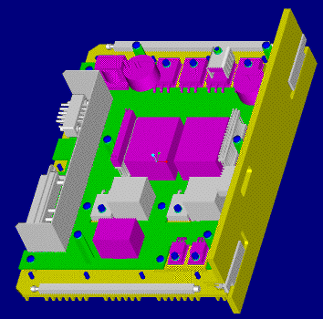
Solid model of the rack mounted communications package modeled with
Coolit
assumptions can lead to inaccurate predictions, especially if an engineer
goes too far in an effort to simplify the analysis, or respond to scheduling
pressures.
"The hand calculations involved some assumptions that really weren't
appropriate," notes Jones, and Coolit picked up these errors."
Coolit automatically determined which assumptions were valid and then
calculated the appropriate values required for the finite differences
codes. When using the conventional approach, Jones had to calculate these
values, by hand using empirical formulas. Coolit also solved the complete
flow field, taking care of all the effects mentioned above.

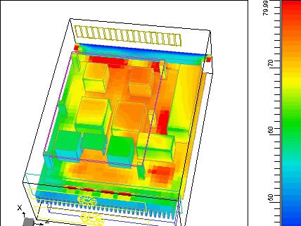
Color-coded thermal plot pinpoints hot spots in power supply design.
Because upper limit of temperature scale is set at 80 deg. C., all components
at or exceeding that value are quickly spotted by their red color.
The CFD tool then pinpointed specific component issues. For example,
it calculated that the power supply heat sink could not adequately dissipate
the heat. Using its simulation capabilities, the tool further showed that
the problem could be easily corrected by increasing the number of heat
sink fins.
Coolit also helped optimize air flow. Initially, air was diverted so
that it would brush both the component and heat sink sides of the power
supplies. CFD analysis showed that by redirecting more flow to the heat
sink side of the assembly, the heat dissipation could be dramatically
improved.
"CFD analysis easily shaved a couple months off the development
cycle by eliminating false design starts, " declares Jones.
CFD has saved Raytheon from a costly and time consuming redesign on other
programs, as well. In one application, a very thin profile box was to
be cooled by a single, very tiny fan. Using Coolit, Jones found one fan
could not handle the thermal load; in fact, 5 fans were needed. Furthermore,
he found the box had to be pressurized in order to provide adequate air
flow across the most troublesome components.

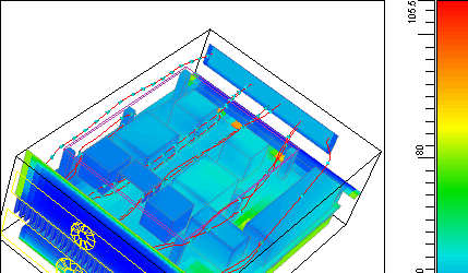
Streamlines show airflow through power supply is unimpeded by component
placement. In this view, the full temperature range of the system is displayed.
Maximum temperature reaches 105.5 deg. C. and occurs in four high-power
FETs that are directly mounted to the finned heat sink in the bottom of
the box.Streamlines show airflow through power supply is unimpeded by
component placement. In this view, the full temperature range of the system
is displayed. Maximum temperature reaches 105.5 deg. C. and occurs in
four high-power FETs that are directly mounted to the finned heat sink
in the bottom of the box.
If conventional analytic techniques had been used, Jones feels the design
changes mostly likely would have progressed in time consuming steps: one
fan, two fans, three fans, etc. until the required 5 fans were reached.
With simulation, the each change were made and the impact calculated in
minutes.
"In my applications, we often have to squeeze several kilowatt transmitters
into relatively small packages that can easily overheat if the cooling
schemes can't dissipated the power," says Jones. "We have to
be careful as to the type of cooling scheme we select. With Coolit, we
can identify flow reversals, determine whether the fan sizes are adequate,
spot areas of overheating---all without building costly prototypes or
reworking drawings every time we want to "test" a change.
To build a CFD model, Jones first sketches the enclosure on his computer
screen and then places components, heat sinks and boards inside. The shapes
are selected from the software's part library, or they may be custom-created
or imported from CAD software.
Component properties, such as thermal conductivity also are selected
from the software library or they can be entered through a dialog box.
Fan curves are drawn or entered through a table. The information can be
entered in any combination of units; the software automatically handles
the necessary conversions.
The output is displayed as 2D and 3D simulations that show airflow and
temperature distribution. Color-coded temperature patterns make hot spots
conspicuous, while velocity vectors indicate the direction and speed of
air movement. The two graphics are overlaid so that the interaction between
air flow and temperature is obvious. If Jones is not satisfied with the
results, he repositions the components or substitutes new ones with different
thermal characteristics.
Coolit also provides on-line animation that enables Jones to "inject
particles" and watch as they travel through the enclosure at a speeds
proportional to the local flow velocities. As the particles travel, they
change colors as temperatures change. While this happens, Jones can rotate
the 3-D image and view it from any angle.
Jones feels that most other CFD packages are focused toward aerodynamic
applications where the user is worried about flow through a jet engine
or pressure on a fuselage, and where the user is concerned with parameters,
such as compressibility effects.
"Electronics engineers have a different class of problems than aerodynamicists,"
he points out. "They are mostly involved with fan-cooled electronics
inside an enclosure, and Coolit is specifically tuned for electronics
applications."
Jones has worked with CFD for over 15 years and has seen the learning
curve for this engineering tool decreased exponentially over the last
10 years.
"Applying Coolit takes no longer than conventional analysis, and
the user receives the benefit of a complex, 3-D thermal analysis that
easily delivers what no physical test can; it identifies the temperature
at every spot within a box."
A physical test is limited by the number of temperature sensors that
are used and where they are placed within the enclosure. If they are put
in the wrong spots, the hot spot may be missed.
Jones declares, "If a company wants to stay ahead of its competition,
it needs to use CFD for its thermal analyses."