|
Encapsulated phase change materials (PCM) are finding an ever wider
application in thermal management of electronics and data centers. PCMs have
high fusion capacity and can absorb large amounts of heat when melting and
release heat when solidifying. PCM component has been implemented in Coolit
and in this white paper we will use it to assess the accuracy of the
implemented model. The geometry of PCM objects is specified in Coolit using
the new PCM Block component or by importing it from CAD. The PCM physical
properties are entered via a dialog and can be general non-linear functions
of the temperature.
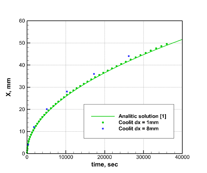
The first problem is the classic problem with analytical solution [1]. An
infinite 100 mm thick slab is initially at 70 oC. The slab's
material properties are: density, ρ = 790 kg/m3, heat
capacity c1 = c2 = 2890 J/kg/K, Tmelting =
55 oC, latent heat, L = 173.4 kJ/kg, and thermal conductivity, k1
= 0.2 W/m/K, k2 = 0.12 W/m/K. The subscript 1 is for solid and 2
for liquid phase. At t = 0 sec the surface temperature is changed to 20 oC
and we calculate the position (X) of the solidification front as a function
of time. Uniform grids with grid cell size 1mm and 8mm were used. Time step
for the first grid was 10 seconds and 100 seconds for the second one.
Additional tests indicated that the selected time steps yielded time-step
independent solutions. Figure 1 shows the Coolit predicted position of the
solidification front against the analytical solution [1].
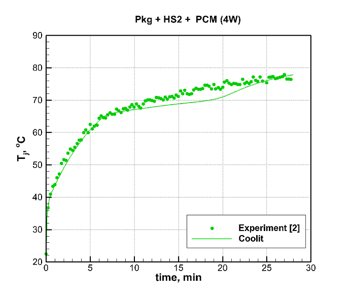
In the second problem we modeled transient cooling of a plastic quad flat
package (QFP) using heat sink with PCM. The system had been previously set
up and experimentally evaluated in [2]. The setup consisted of a thermally
enhanced QFP package, 14 x 14 mm and 64 leads, mounted on top of a printed
circuit board (PCB). The die was placed upside on an attached die paddle
covered outside with epoxy molding compound. Heat spreader to enhance
performance of the QFP package was placed on top of the die. The test is
described in more detail in EIA/JESD51-2 standard [3]. We modeled large
plate fin heat sink (HS2), 31x31x10 mm with 10 plate fins and filled with
molten PCM (paraffin). The input power in this experiment was 4 W.
The QFP die temperature measured in experiment [2] is shown in Figure 2
against results predicted by Coolit. The uncertainty error in experiment was
estimated to be within 5% [2]. The 1.1 M grid cell model was calculated with
2 sec time steps.
References:
1. H.S. Carslaw
and J.C. Jaeger, Conduction of Heat in Solids, 2nd edn. Clarendon Press,
Oxford, p. 285, 1959.
2. R. Kandasamy,
X. Q. Wang, A. S. Mujumdar, Transient cooling of electronics using phase change
material (PCM)-based heat sinks, Applied Thermal Engineering 28, 2008.
3. EIA/JESD51-2,
Integrated circuits thermal test method environment conditions natural
convection (still air).
|