|
To maximize module count while minimizing footprint, Honeywell engineers developing
a new process control system vertically stacked the I/O and
Controller modules. But vertical stacking created an overheating problem. Cool air
entering the bottom of the cabinet would grow warmer as it traveled upward from one
module to the next. By the time it reached the upper portion of the stack, the air would
be so hot that it would cause modules to overheat. .
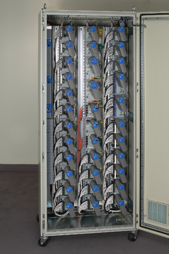
The system contains 36 modules stacked into three columns of 12 modules
each. Design specifications set the ambient air temperature at 50 C, while many
components are rated at 70 C. To keep components from exceeding this limit, more fans and
vents would be required, but this was not an option because fans reduce reliability, add
noise, and pull in contaminants. Air enters through vents at the bottom of the cabinet
and exhausts through the fans at the top. Additional venting on the sides was not
possible because the equipment is often joined side by side.
With the obvious fixes off-limits, Honeywell engineers reasoned that if
each board were tilted at the appropriate angle, unheated air could enter at the bottom
right side of the module, flow across it and exit at the top left side. Each module,
regardless of its vertical position in the stack, would be cooled by unheated air
entering from the bottom.
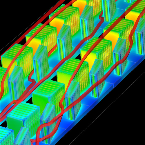
Since there was no time to build a physical prototype to prove the concept,
engineers used Coolit software. The analysis predicted that if the modules
were slanted 18 deg and stacked relatively close (1/4") together in the
vertical direction, cool air would reach each of the 36 modules. There would
be no co-mingling of hot and cool air from one column to the next. Verifying
the design through physical prototyping would have taken a minimum of 2-3
months. Time-to-market was critical and Coolit delivered.
Tilting the modules solved the airflow problem, but there was still one
more thermal challenge. One I/O module dissipated almost twice as much heat
as the others. The problem module contained 16 high-heat-dissipating FETs
(Field Effect Transistors) and heat from the FETs was being transported via
the copper traces across the length of the board to other devices, negatively
impacting their reliability. Engineers tried to fix the problem by spreading
the FETs evenly over the board surface, but Coolit analysis predicted that
some devices would still be subjected to excessive heat.
The next proposal was to thermally isolate, the high-heat-producing
devices from the rest of the board. A design was developed in which all FETs
were separated on the board from the other devices with a thermal barrier.
The concept worked. Heat passing from the FETs to the opposite end of the
board was dramatically reduced, and Coolit analysis verified that components
on both sides of the barrier remained within their operating limits.
Using computer modeling was essential. It would take hundreds of boards to
check out a design, and it takes months to get them fabricated, assembled,
and tested. Then they would be shipped to several Honeywell sites around the
world for complete system testing. By the time a problem would be identified
and boards redesigned, a minimum of six months would have passed and hundreds
of boards would be thrown away. Developing this design using thermal
simulation saved Honeywell a minimum 6 months and considerable money.
|